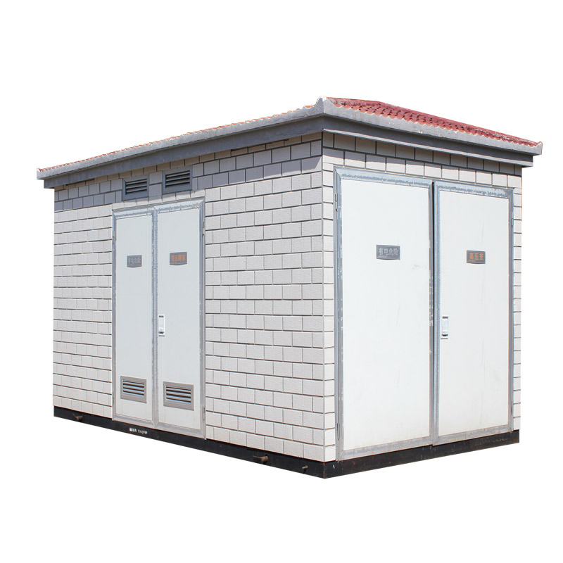
YBM prefabricated substation
The base can be designed as either a caisson type or a flat steel structure.
Four lifting shafts are arranged on the sides, and the base surface is specially treated for corrosion resistance.
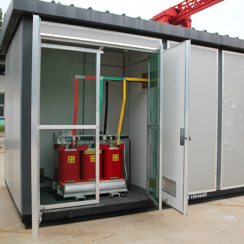
The frame adopts a “Mu”-shaped and “Pin”-shaped structure, divided into high-voltage, transformer, and low-voltage chambers.
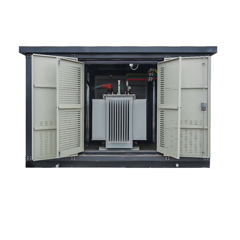
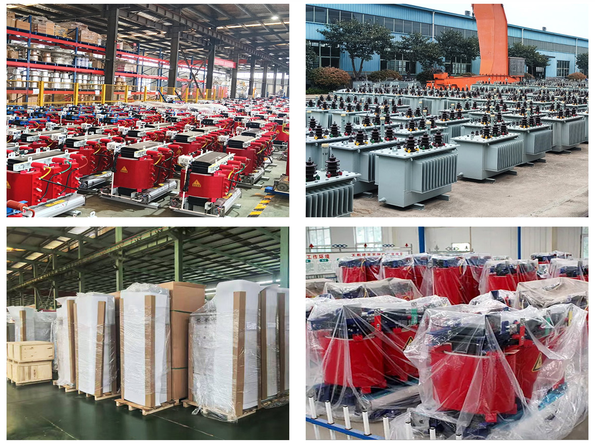
According to user requirements, the distribution transformer can be equipped as an oil-immersed, low-loss, energy-saving power transformer or as a dry-type transformer.
Product Description
The YBM prefabricated substation (box-type substation) integrates high-voltage electrical equipment, transformers, and low-voltage electrical equipment into a compact, complete power distribution unit. Also known as a European-style box-type substation, it is widely used in urban high-rise buildings, residential communities, urban and rural infrastructure, high-tech zones, small and medium-sized factories, mines, oil fields, and temporary construction sites for receiving and distributing electrical energy in the distribution network.
Product Features
The YBM prefabricated substation is highly integrated, compact in size, safe, reliable, easy to maintain, and portable. Compared with traditional civil substations, it typically requires only 1/10 to 1/5 of the floor space for the same capacity, greatly reducing design, construction workload, and overall costs. It can be applied in ring network, dual power supply, or radial terminal distribution systems. As a new type of integrated equipment, it is widely adopted in the construction and upgrading of urban and rural substations.
Environmental Conditions
Altitude ≤ 1000 meters.
Ambient temperature: maximum +40°C, minimum -25°C, with a 24-hour average not exceeding +35°C.
Maximum outdoor wind speed: 35 m/s.
Relative humidity ≤ 90% (at +25°C).
Seismic conditions: horizontal acceleration ≤ 0.4 m/s², vertical acceleration ≤ 0.2 m/s².
The installation site must be free from fire, explosion hazards, severe pollution, chemical corrosion, or intense vibration.
Structural Features
The unit is composed of a high-voltage distribution compartment, transformer compartment, and low-voltage distribution compartment, each with complete functionality. The high-voltage side supports multiple configurations, including ring network, terminal, and dual power supply systems, and can be equipped with high-voltage metering devices. Transformers may include S7, S9, or other low-loss oil-immersed and dry-type models, with self-starting forced air cooling systems and lighting installed. The low-voltage compartment can be configured with panel-mounted or cabinet-mounted systems according to user needs, offering functions such as power distribution, lighting, reactive power compensation, energy metering, and monitoring to improve power quality and efficiency.
The high-voltage room adopts a compact design with comprehensive interlocking features to prevent misoperation. Optional transformer rails allow easy movement through side doors. Each compartment is equipped with automatic lighting, and all components in both high- and low-voltage rooms are reliable, easy to operate, and convenient to maintain.
Both natural and forced ventilation systems are employed. Ventilation ducts in the transformer and low-voltage compartments, combined with temperature-controlled exhaust fans, ensure effective cooling and reliable transformer operation under full load.
The enclosure is designed to resist rain and dust, made of treated special steel or aluminum alloy plates. With excellent anti-corrosion, waterproof, and dustproof performance, the box is durable for long-term outdoor use, combining reliability with an attractive appearance.
Item | unit | |||
Rated frequency | Hz | 50 | ||
Rated voltage | kV | 10 | 35 | |
High-voltage components | Maximum operating voltage | kV | 11.5 | 40.5 |
Rated current | A | 400 630 12S0 1600 | ||
Power frequency withstand voltage (to ground and between phases/isolating distance) | kV | 42/48 | 95/115 | |
Lightning impulse withstand voltage (to ground and between phases/isolating distance) | kv | 75/85 | 18S/215 | |
Rated short-circuit breaking current (current limiting circuit breaker) | kA | 31.5 | ||
Rated voltage | kV | 10 | 35 | |
Rated capacity | kVA | 30—150 | ||
Transformer unit | Tap range | % | ±2×2.5% ±5% | |
Connection group | YynO | Dyn11 | ||
Impedance voltage | % | 4 4.5 6 8 | ||
Rated voltage | V | 220 380 660 | ||
Low-voltage unit | Main circuit rated current | A | 50-6300 | |
Branch current | A | 5—800 | ||
Mechanical characteristics | Protection level (conventional products) | High and low voltage rooms: IP33 | Transformer room: IP23 | |
Noise level | dB | ≤50 |
