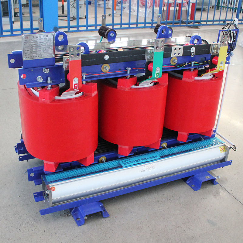
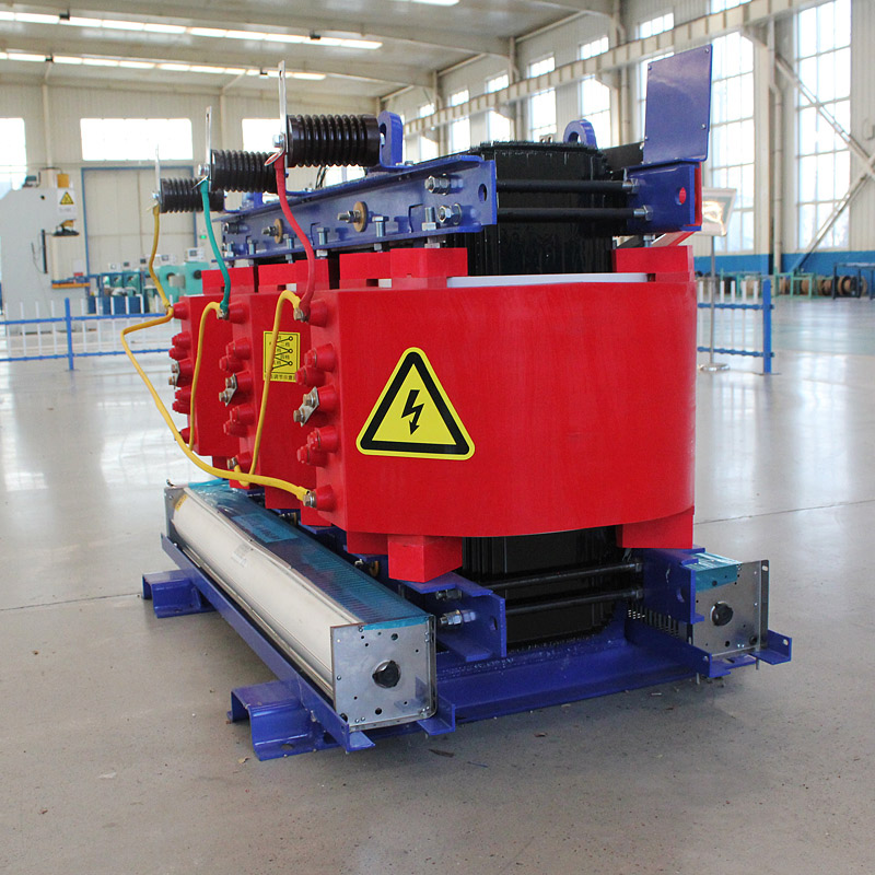
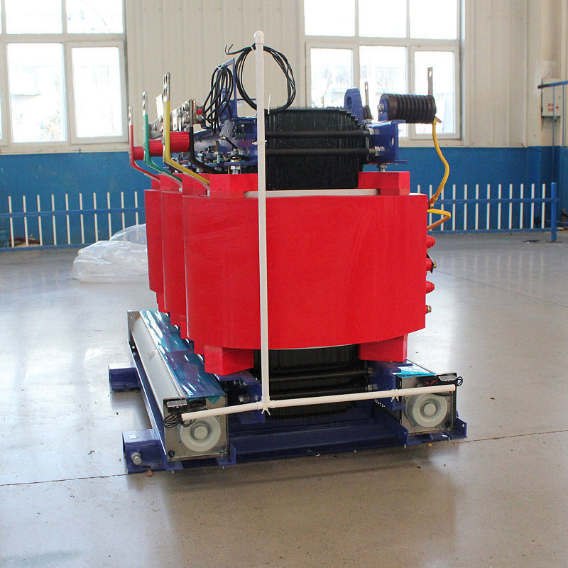
Scb12 80kVA 10kv Dry Type Transformer Level 3 Energy Efficiency
High Safety and Reliability: The epoxy resin dry-type design ensures excellent insulation performance, flame resistance, and improved operational safety in various power distribution environments.
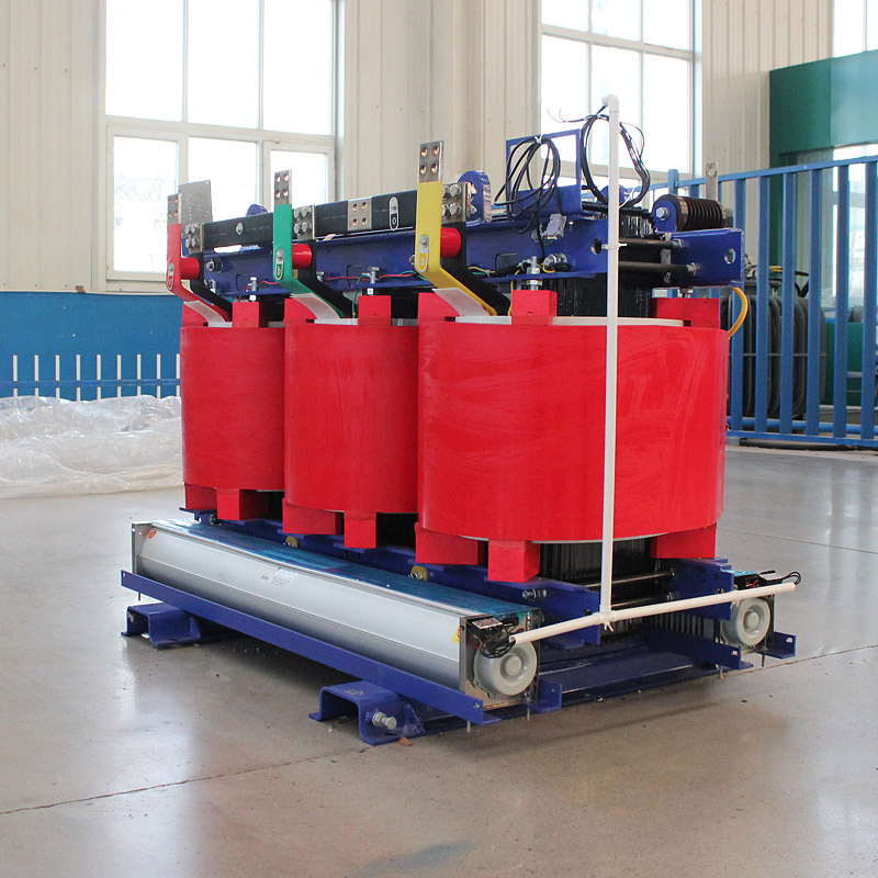
Efficient Copper-Foil Winding Structure: The copper-foil wound coils provide strong mechanical strength, better short-circuit resistance, and enhanced transformer stability during operation.
Ideal for Medium and Small Substations: As a key transformer for medium- and small-sized substations, it ensures stable and efficient power distribution for industrial, agricultural, and lighting applications.
Environmentally Friendly and Low Maintenance: The dry-type, fully cast epoxy structure eliminates the need for transformer oil, reducing maintenance requirements and making it suitable for indoor and environmentally sensitive locations.
Introduction to SCB12-80kVA 10/0.4kV Dry-Type Distribution Transformer
SCB12 refers to an epoxy resin dry-type transformer. S indicates three-phase, C indicates epoxy resin cast dry-type transformer, B indicates the transformer coils are wound with copper foil, 12 is the transformer performance level code, and 10/0.4 indicates the transformer's rated high-voltage side is 10kV and the low-voltage side is 0.4kV.
This kind of product is applied to power system, it is the main transformer equipment of medium and small-sized transformer substation, supplies power distribution, power illumination for the industry and agriculture.
Advantages of the SCB12-80KVA Dry-Type Transformer:
- Small size and light weight;
- Air-cooled, eliminating the need for insulating oil, reducing pollution, and facilitating maintenance and safety;
- Enables a constant amplitude voltage output from the secondary side of the SCB12 dry-type transformer;
- Improves power quality, providing sinusoidal input current and output voltage with unity power factor. Furthermore, the voltage and current on both sides of the SCB12 dry-type transformer are controllable, allowing for arbitrary adjustment of the power factor.

| Rated capacity(kVA) | Voltage | Maximum no-load losses (kW) | Maximum on-load losses(kW) | Short circuit impedance Uk (% ) |
| 30 | 0.15 | 0.71 | 4 | |
| 50 | 0.215 | 1 | 4 | |
| 63 | 0.295 | 1.38 | 4 | |
| 80 | 0.32 | 1.57 | 4 | |
| 100 | 0.375 | 1.85 | 4 | |
| 125 | 0.43 | 2.13 | 4 | |
| 160 | 0.495 | 2.53 | 4 | |
| 200 | 6 | 0.575 | 2.76 | 4 |
| 250 | 6.3 | 0.705 | 3.47 | 4 |
| 315 | 10 | 0.785 | 3.99 | 4 |
| 400 | 10.5 | 0.93 | 4.88 | 4 |
| 500 | 11 | 1.07 | 5.88 | 4 |
| 630 | 1.04 | 5.96 | 6 | |
| 800 | 1.215 | 6.96 | 6 | |
| 1000 | 1.415 | 8.13 | 6 | |
| 1250 | 1.67 | 9.69 | 6 | |
| 1600 | 1.96 | 11.73 | 6 | |
| 2000 | 2.44 | 14.45 | 6 | |
| 2500 | 3.88 | 17.17 | 6 |